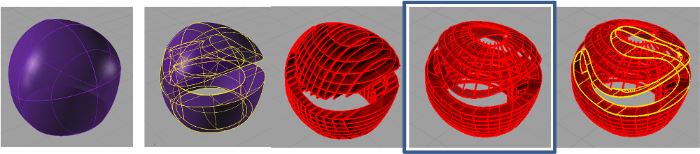
One of the exercises we have been developing with the laser cutter is the design of a stand generated from elements attached to each other by means of press fit system.
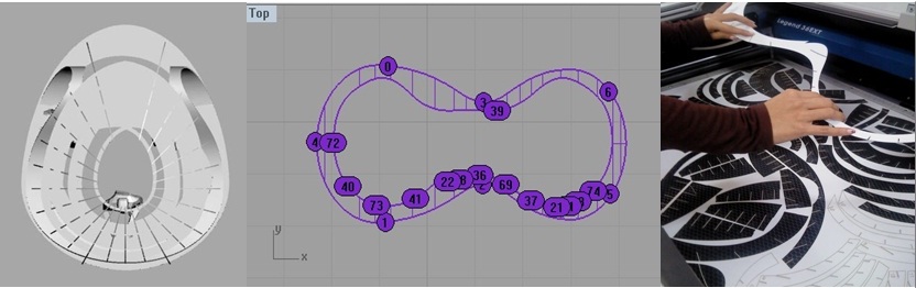
CAD: modeling 3d and measure using the Rhino. Deployment of the parts is in relation to the work area of the machine

Measure:
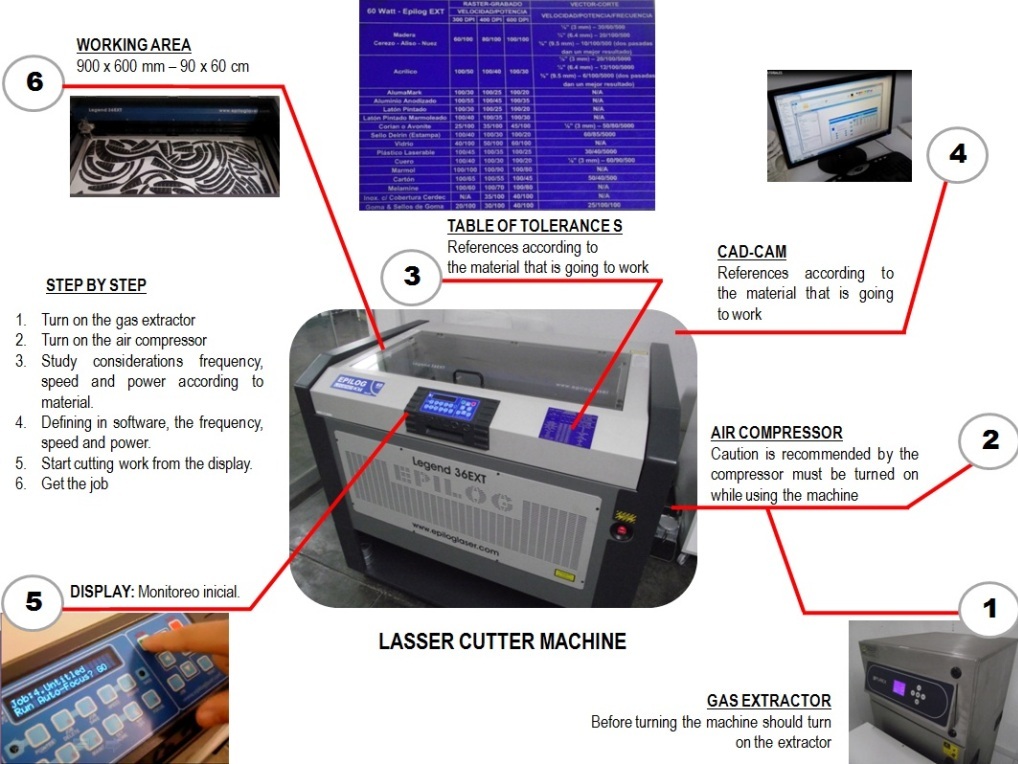
Machine: Laser Cutter - Epilog
Material: carboard “1mm”
Before sending your file, we started testing with the material we have chosen. Usually in the market sell the material with a thickness, which is not safe. Therefore we must always check the thickness of the material with the vernier.
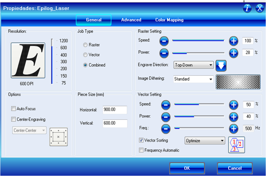
Having the exact measure we can study the speed, power and frequency for machining, in order to differentiate the cut of the raster.

The configuration of print settings is simple. So before following the instructions, keep in mind: what do we do? what material we use?
In this case we use the Rhino, as it gives us the option to send our file to cut directly by supplying the driver use the machine to machine (in this case the Epilog laser). It is also possible to use other software to send to the court, such as Corel Draw

Difficulties
The hardest part of the machining process was to generate a continuous curve with a very thin thickness. Therefore, had to cut into two parts.


Prototype: Assembly process
